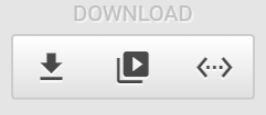
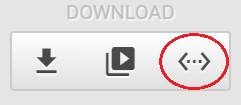
DOWNLOAD
There are three buttons in this category:
Download
This button downloads the HMI design to Ubique Panel’s control board:
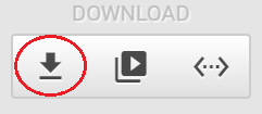
Please use a USB cable to connect to the control board and then press this button, the design can be downloaded into the board.
When download is successful, a pop-up window will show up:
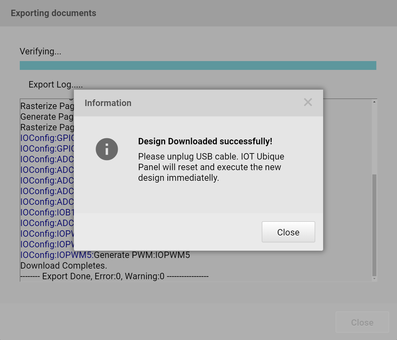
This pop-up window informs the user that the HMI is successfully downloaded to Ubique Panel. The download time varies according to the sizes of the images. If any error occurs during the download process, the error message will be shown and the download will be stopped immediately.
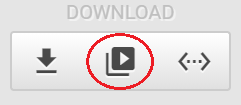
Launch Simulator
The middle button is to launch ADE’s built-in Simulator:
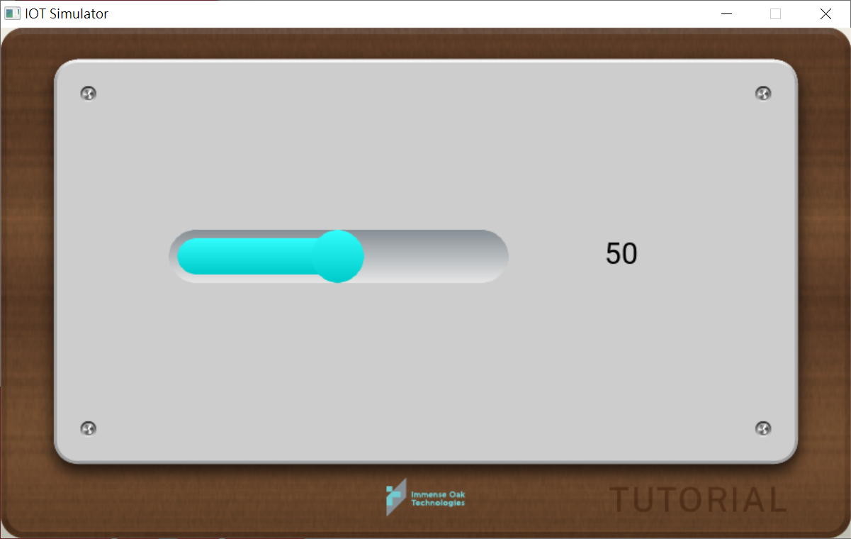
The built-in simulator allows users to simulate their HMI design in ADE. In this simulator, users can use mouse to interact with the HMI design. This simulator supports What-You-See-Is-What-You-Get. The resolution of the simulator meets that of the target Ubique Panel. However, the color of HMI in the simulator can not be 100% the same as that of Ubique Panel.
The built-in simulator cannot simulate the I/O functionalities like GPIO, PWM and ADC. On the other hand, the simulator supports the communcation protocol used by Ubique Panel.
Launch Messegner
The messager can be used to communicated with the connected Ubique Panel or with the built-in simulator.
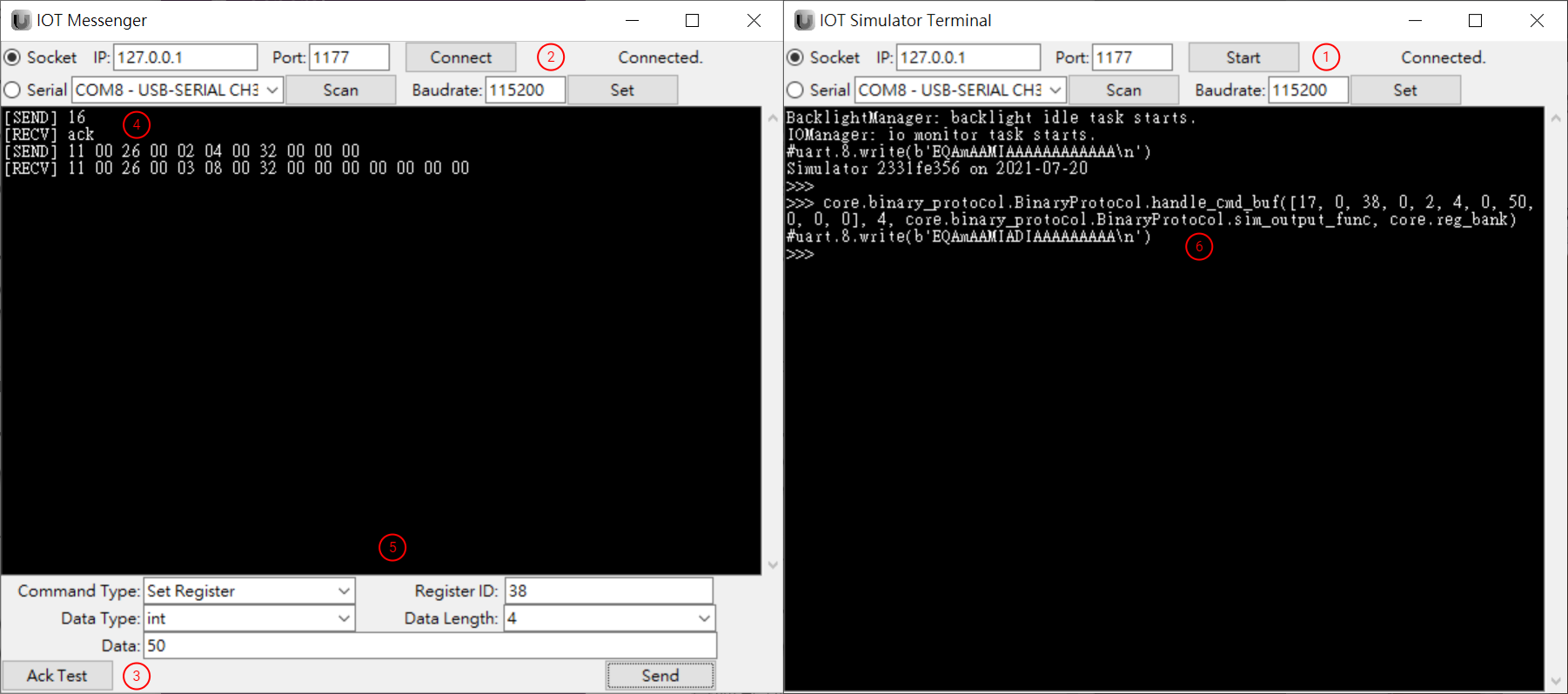
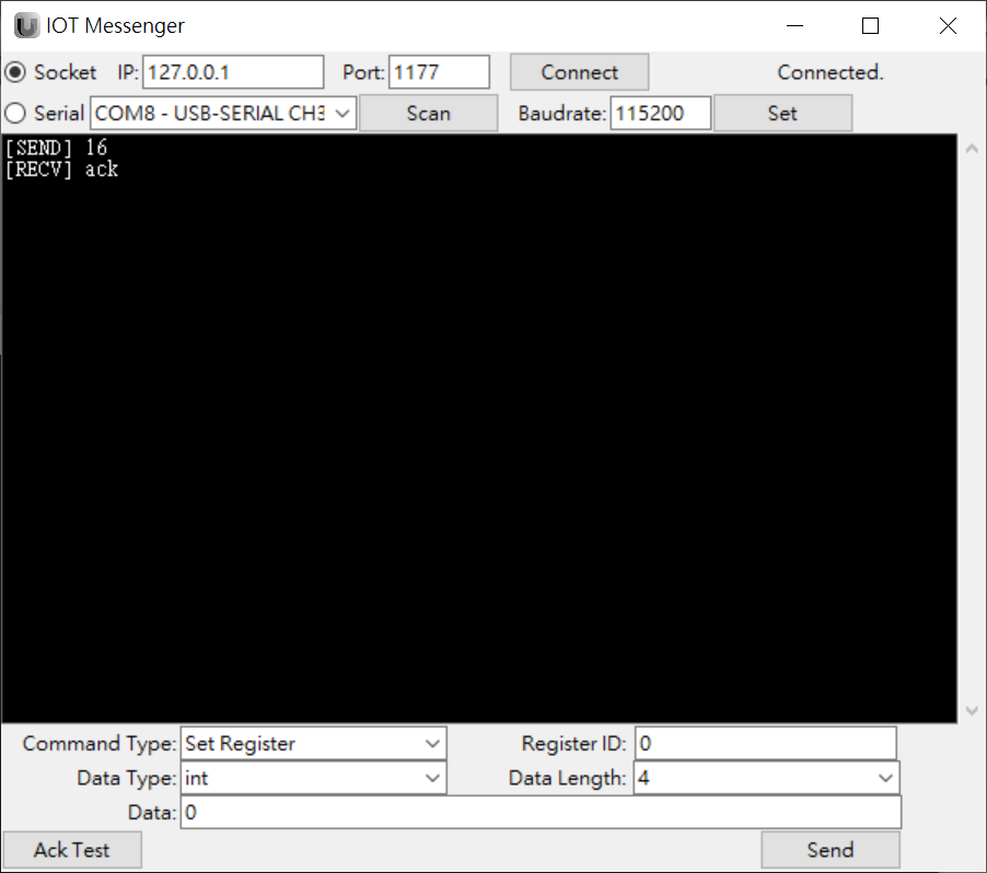
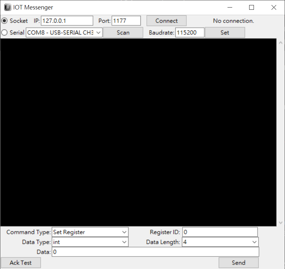
After Launch Messenger button is pressed, “IOT Messenger” dialog box will appear:
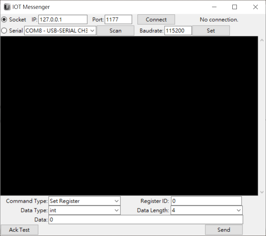
In this dialog box, users can use PC’s serial port and network interface to connect to Ubique Panel or the built-in simulator. The communication protocol is based on IOT’s proprietary protocol and will be described in details later. The messenger emulates the communication between an external MCU and the Ubique Panel via a UART interface.
Messenger offers two communication methods: Network Socket and Serial Port.
If Network Socket is selected, IP addfress, Port number must be set; if Serial Port is used, Baudrate must be set.
-
Command Type: Set Register is to write a value to a register; Get Register is to read the content of a register.
-
Register ID: Set the ID of the reigster to which commands are performed.
-
Data Type: Select the data type. This is valid only during Set Register operations.
-
Data Length: Set the data length in bytes. This is valid only during Set Register operations.
-
Data: The data itself. This is valid only during Set Register operations.
-
Ack Test: Verifying the connection. Please refer to Ack Test.
The communication between the built-in simulator and Ubique Panel will be described in details:
Use Messenger to communicate with the built-in simulator
-
First, please open a design in ADE.
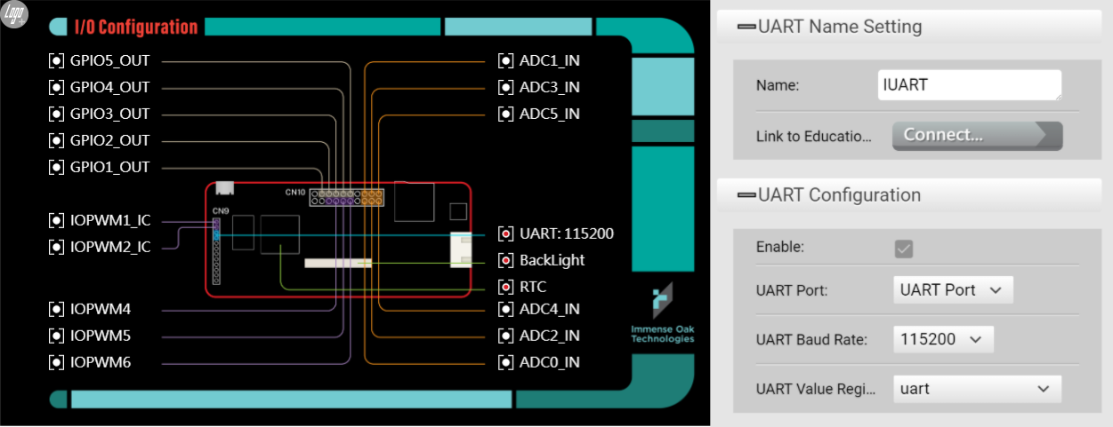
In IOConfig page, please make sure that UART is activated, Baudrate is accurate and UART Value Register is bound to a register.
-
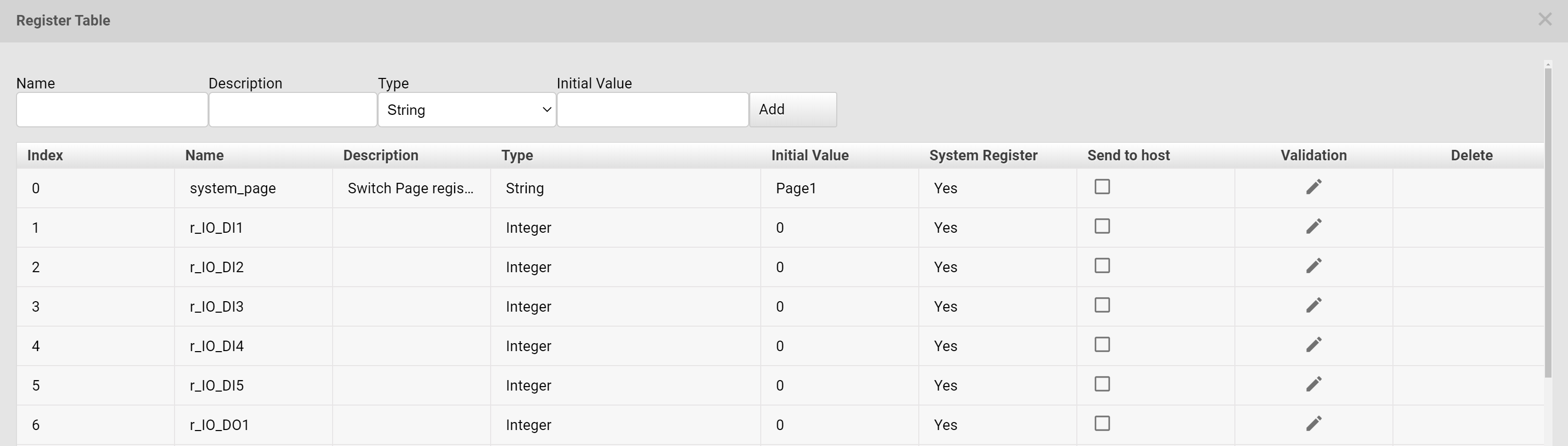
In the Register Table, please check Sent to host for those registers that will be used for communication.
-
Launch Messegner and perform the following operations:
-
Set Socket
-
Click Connect. If the connection is ready, a pop-up message box tells users if the connection is valid or not.
-
Click Ack Test then Messeenger will send out a connection verification command. If the simulator receives the command successfully, then a ACK command is sent back to the messenger.
-
If the connection is ready, ACK will be recevied by the messenger after sending a command.
-
For communication commands, please refer to IOT Protocol more more details.
When Set Register is used, users have to enter the register ID and Data Type. The ID and the data type must match those of the registers set in ADE.
-
Simulator takes the communication commands and change the corresponding registers’s value. Subsequently, the value change is reflected on the widgets in Simulator.
-
Communication between Messenger and Ubique Panel
-
Please download the HMI design to Ubique Panel.
-
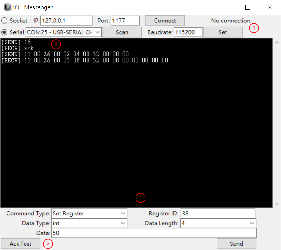
Please use a USB-to-UART cable to connect PC’s USB port with Ubiqu Panel’s UART.
-
Launch Messenger.
-
Set the Serial Port. Users can use Scan for scanning the available serial ports. Then a correct baudrate must be set as well.
-
Clik Ack Test for testing the connectivity.
-
If connection is normal, ack message is received.
-
Set up and send communication instructions. Please refer to IOT Protocol for more details.
-
-
Then you can see the reaction in Ubique Panel.
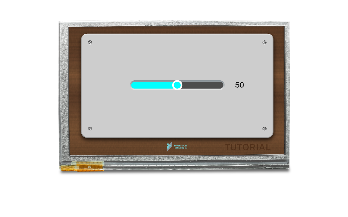
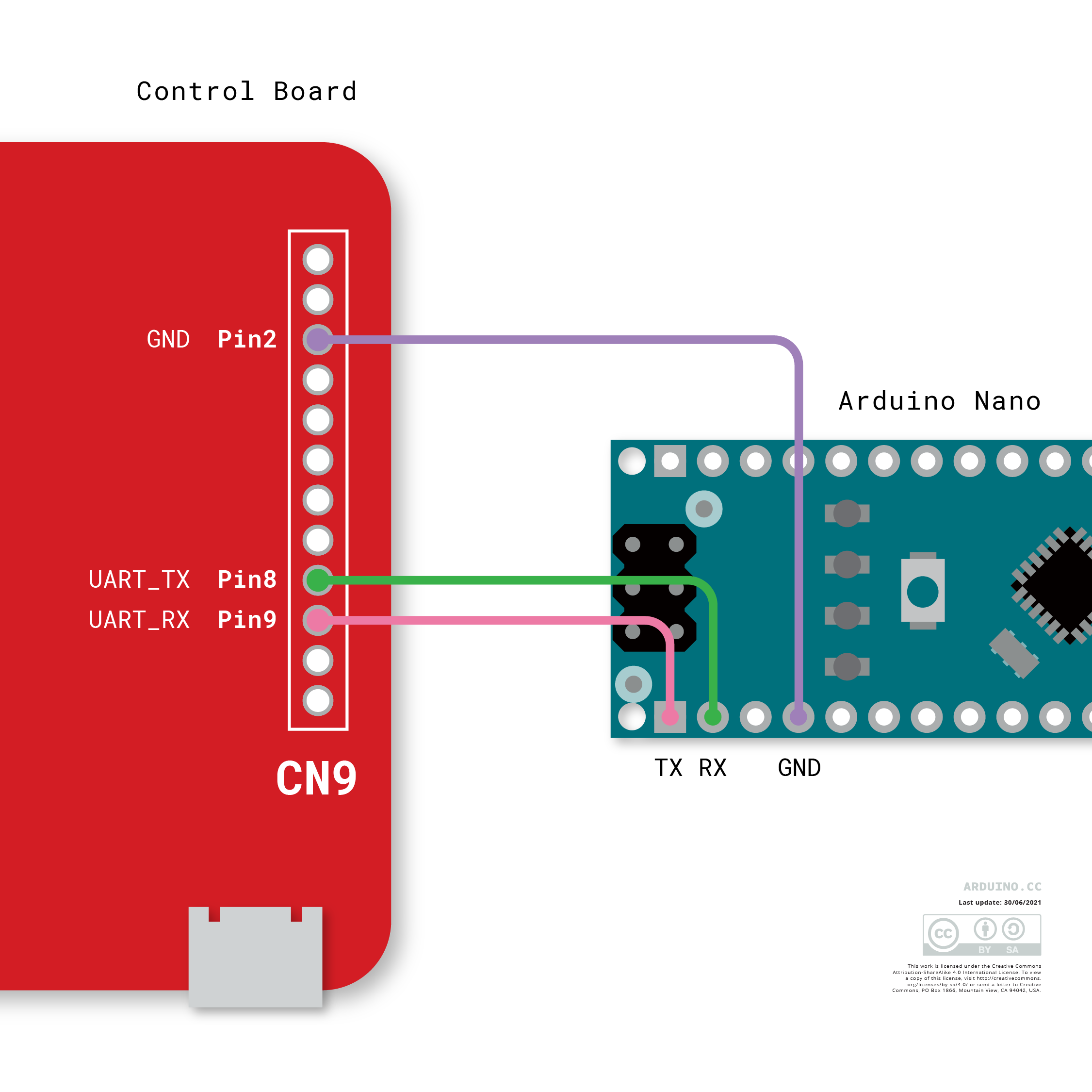
Communication between Ubique Panel and MCU
-
First, please prepare an ADE project and set the registers up properly. Please refer to our communication protocol IOT Protocol for writing the Arduino code. Then the data can be sent to the registers with designated IDs.
-
Then, connect IOT’s control board with Aurdino. Make sure you connect RX, TX and GND.
-
Please download ADE project to our control board and Arduino program to the Arduino board. Turn on the power, the commuication starts.
IOT’s UART Protocol
-
Command Format
Command Lead Byte Type Byte Register ID Low Byte Register ID High Byte Tailing Bytes Set Register 0x11 0x00 0x00~0xFF 0x00~0xFF Data Payload Get Register 0x11 0x01 0x00~0xFF 0x00~0xFF N/A -
Data Payload Format
Payload Type ID Byte Length Low Byte Length High Byte Tailing Bytes Boolean 0x00 0x01 0x00 Data Bytes String 0x01 0x01~0xFF 0x00~0xFF Data Bytes Integer 0x02 0x01/02/04/08 0x00 Data Bytes Unsigned Integer 0x03 0x01/02/04/08 0x00 Data Bytes Floating Point 0x04 0x04/08 0x00 Data Bytes -
Data Bytes are of the Little-Endian Format
For IOT’s Arduino Library, please refer to IOT Binary Protocol for more details.
Ack Test
In order to ensure that the connection is established properly, users can click Ack Test. Once clicked, the system will send out 16. If ack is received, the the connection is in order; otherwise, the connection is not established yet.
-
Use Network Socket
If connection fails, it is recommended to check the IP address and the port number are correctly assigned. Once assigned, users need to click Connect to establish connection.
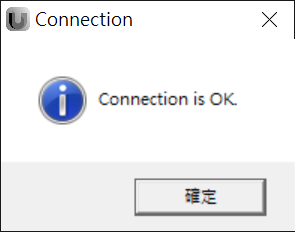
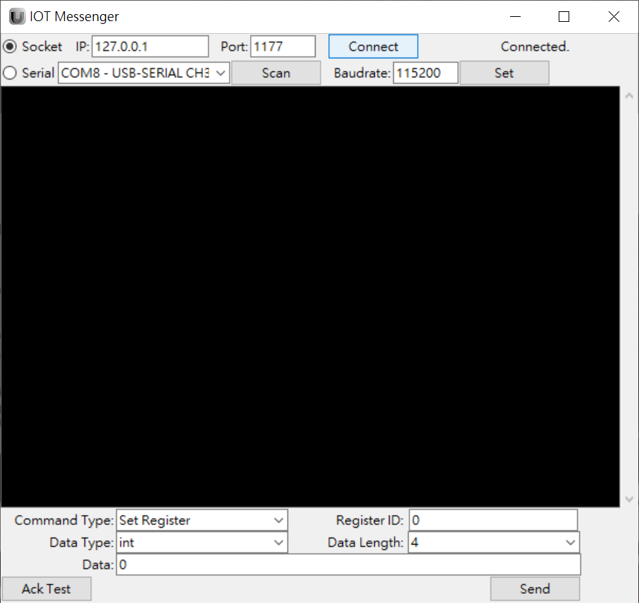
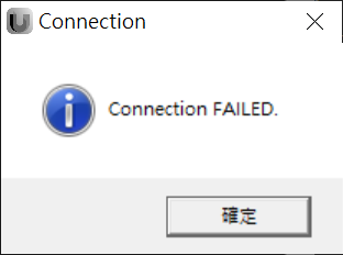
If the connection is established property, Connection is OK message is prompted. Aferward, Connected is shown at the right-hand side of the Socket command row.
If connection is not established, Connection FAILED message is prompted. Afterward, No Connection is show at the right-hand side of the Socket command row.
-
Use Serial Port
If the connection is not established, please check the serial port assignment and baudrate setting. Then press Set for establishing connection.