Speical Page
When users open a new deisgn, two pages by default show up. One is a blank page for HMI design and the other page is the I/O Configuration page, which allows users to configure I/O functionalities such as GPIO, PWM and ADC.
To learn more about this I/O configuration page, users can watch our educational video:
-
Educational Video
I/O Configuration page:
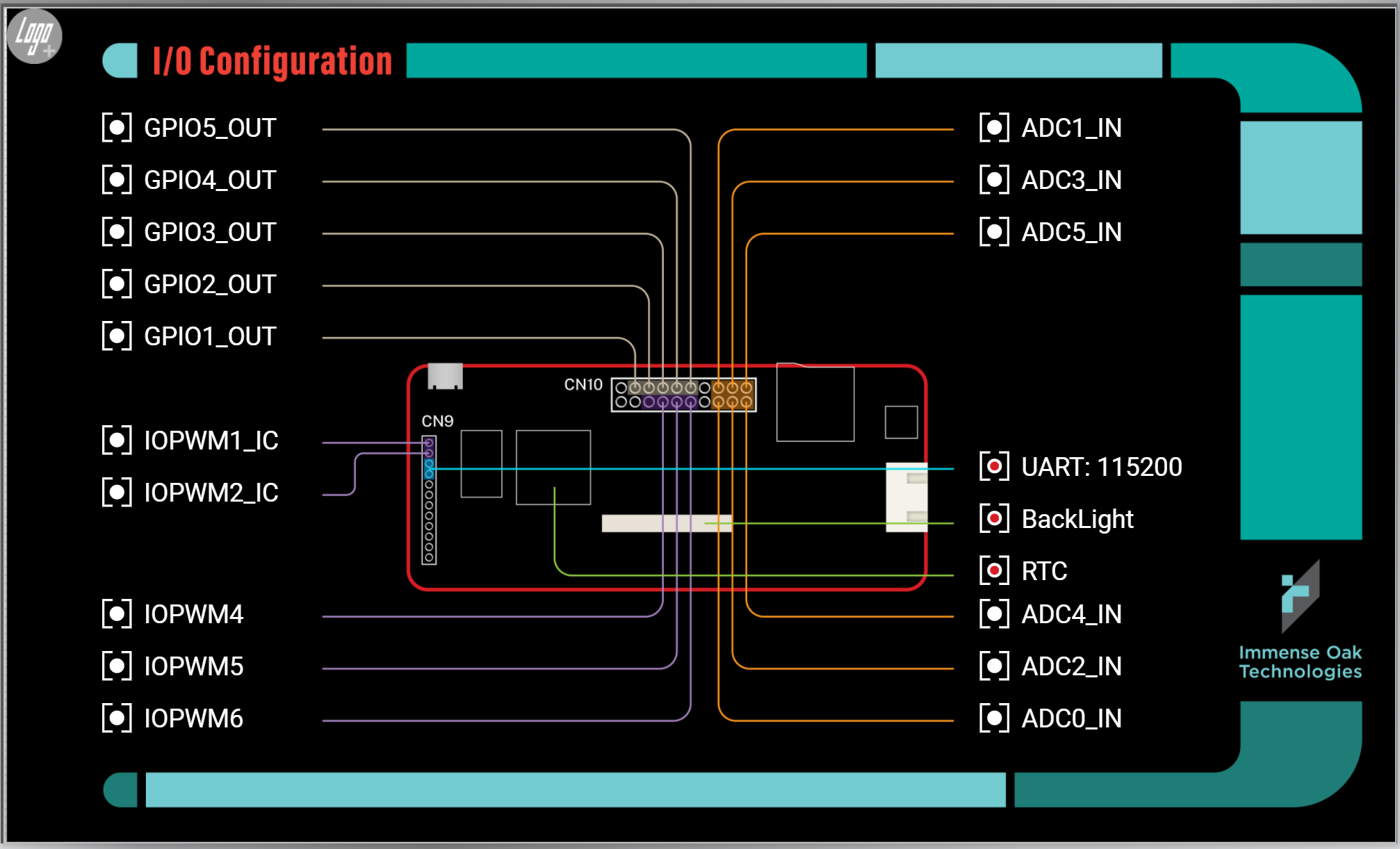
In this page, several I/O functions can be set: GPIO, PWM, Input Capture, ADC, UART, Backlight Control, RTC and Logo.
GPIO
Digital Input/Output Pins: The name starts with GPIO with a serial number attached (Ubique Panel Datasheet ), then an underline is added along with IN or OUT for specifying input or ouput pin.
The red dot on the left-hand size of the pin flags if this pin is activated or not.
Different products have different I/O pin assignments or function. Please refer to the product’s datasheet for more details.
For instructions on how to setup GPIO, please refer to GPIO.
PWM/Input Capture
PWM/Input Capture Pin: The name starts with IPOWM with a serial number (詳見 Ubique Panel Datasheet ).
Input Capture counts the number of input pulses within a time frame. When a pin is assigned to be Input Caputre, “_IC” is added as the suffix.
The red dot on the left-hand side flags if this pin is activated or not.
For more details regarding PWM/Input Capture mode, please refer to PWM/Input Capture for more details.
ADC
ADC Pin: The name starts with ADC with a serial number and “_IN” is added as the suffix. (Please refer to Ubique Panel Datasheet )
The red dot on the left-hand side flags if this pin is activated or not.
For more details regarding ADC, please refer to ADC for more details.
UART
UART: It is used for communication. For the pin assignment and the communication protocl, please refer to Ubique Panel Datasheet for more details.
The red dot on the left-hand side flags if this UART is activated or not. The UART is on by default.
For more details regarding this UART interface, please refer to UART for more details.
BackLight
BackLight: This is to control the brightness of the LCM backlight and the screen sleep mode funtion.
For more dettails regarding BackLight, please refer to Backlight.
RTC
RTC: Activating the RTC (Real Time Clock) function.
For more details regarding RTC, please refer toRTC.
Logo
The Logo widget:

This widget allows users to add their own logo for display right after powering on. The display time can be set in this widget as well.
For more details regarding Logo, please refer to Logo.